Running DeepSeek-R1 on refubrished blade server: 03 Power+
Welcome back, Previous part here: Running DeepSeek-R1 on refubrished blade server: 02 Power.
Introduction/Plan
I this part I am planning to design proper PCB for power delivery and communicating with motherboard. Note:
- I am not trying to re-implement SATA port connectors, this doesn't make a lot of sense right now.
- Should be able to push 500W at 12V (~42A), based on calculation from previous part
- Should be able to toggle power on/power off state of the server
- Should provide monitoring of ethernet and overheat led.
- Nice to have - be able to communicate via SMBus (I2C)
Starting with 42A, thats a lot for PCB.
Handling currents
Calculation is actually quite easy, but there is a lot of online calculators:
- https://www.advancedpcb.com/en-us/tools/trace-width-calculator/
- https://www.digikey.ca/en/resources/conversion-calculators/conversion-calculator-pcb-trace-width
- https://www.pcbway.com/pcb_prototype/trace-width-calculator.html
All of them are based on standard published by IPC: IPC-2221A Appendix B, page 116, if you are interested in math and methods behind it
With 40A of current; 2oz copper and allowing Temperature rise of 40C we get something around of 10mm width and power loss of 1W. 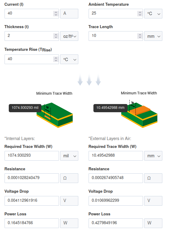
Required pins
Now, going back to data that known about motherboard connector, and skipping unconnected traces, SATA cabling and 5V rail, we have:
| S connector | Voltage in S5/G2 | Function |
|---|---|---|
| 1 | 3.3V | |
| 2 | 4.8V | |
| 3 | 0V | |
| 4 | 0V | PWR_OK |
| 6 | 3.3V | SMBCLK |
| 7 | 3.2V | SMBDAT |
| 8 | 0V | |
| 14 | 4.82V | |
| 15 | 3.1V | |
| 16 | 3.1V | |
| 17 | 0V | |
| 18 | 0.2V-4.8V | UID_LED |
| 19 | 2.8V | |
| 20 | 0.2-4.8V | ETH_LED |
Categorizing voltages, we get: 6x3.3V pins: 1,6,7,15,16,19 that can be connected to MCU directly, since their voltage is <3.3V. 8x5V pins: 2,3,4,8,14,17,18,20 that should be level converted to be used safely.
Additional nice to have: is to add voltage monitoring on 12V rail to pull down PWR_OK in cases when 12V is under ATX spec to protect motherboard and it's pci devices, small voltage divider would work ok for this, this would require 1 analog pin. So, in total 15 pins needed.
PCB design
| Item | Func |
|---|---|
| ESP32-S2-DevKitC-1 | MCU |
| TXS0108EPWR | Logic level shifter |
| DD2712SA | DC-DC Step-down Buck Converter |
| 0805 SMD Resistors |
For design kicad was used. Schematic: 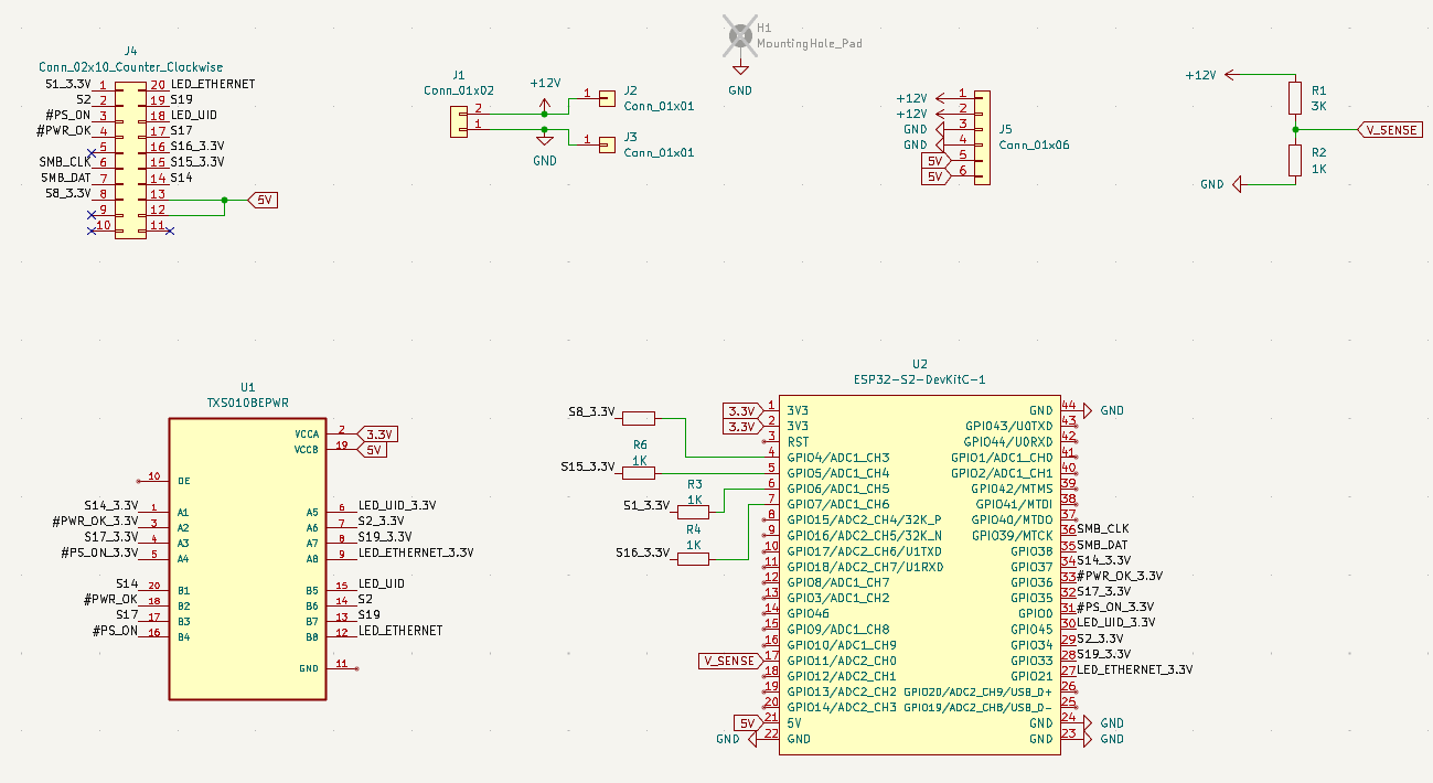
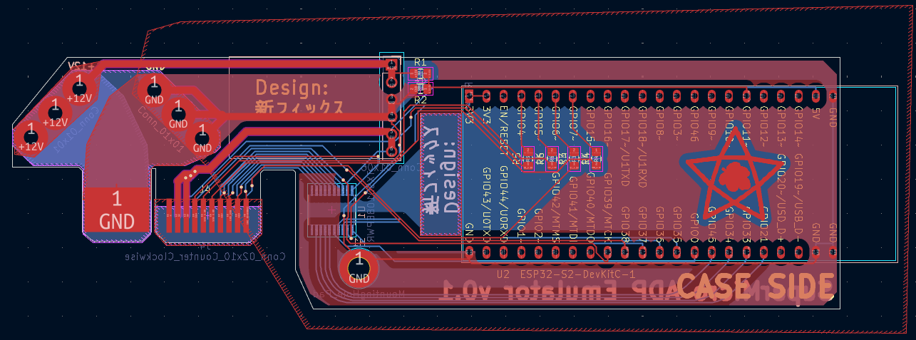 And rendered version:
 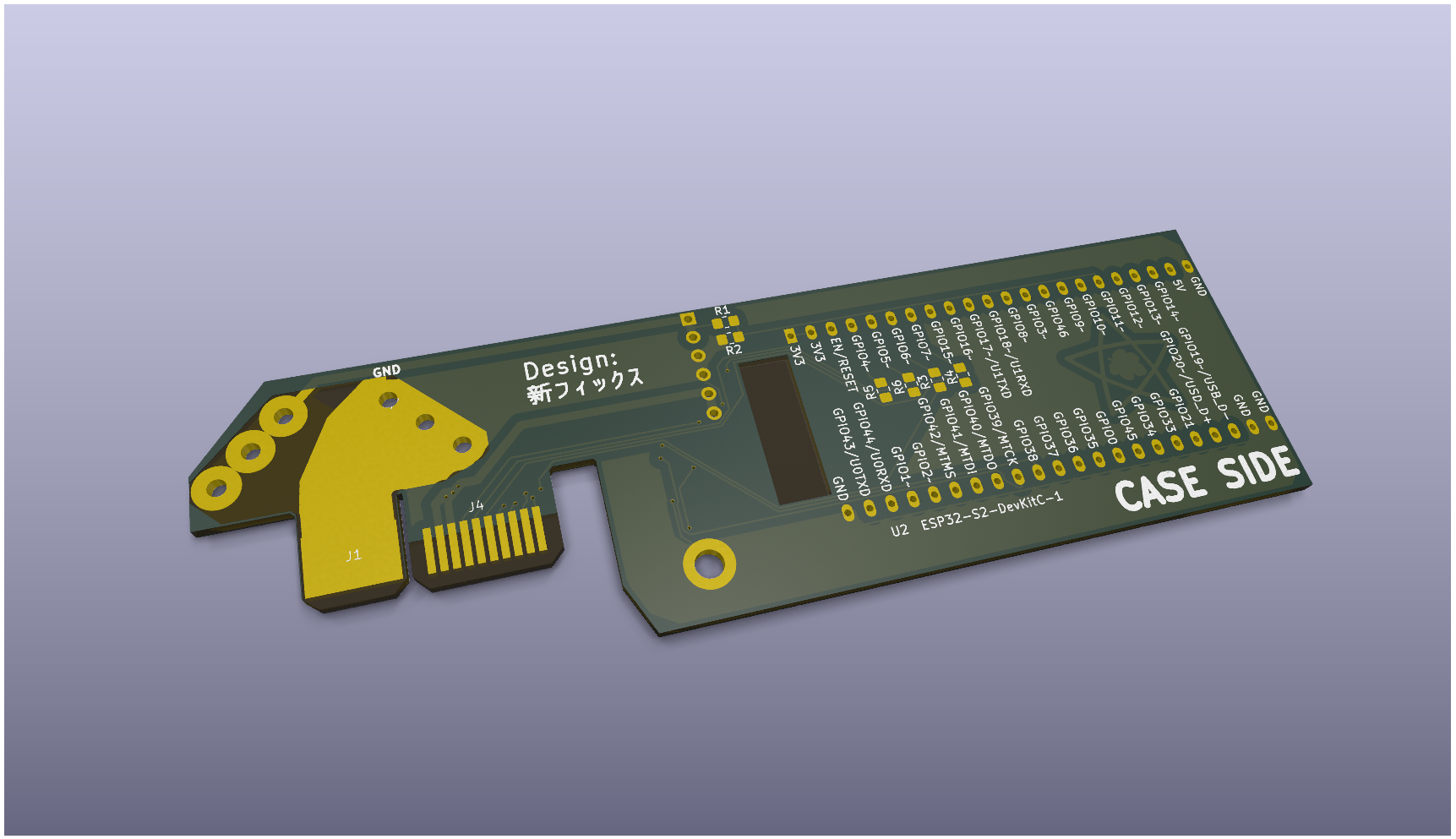 I ordered PCBs from Allpcb, because it was the cheapest one to get 2oz copper PCB.
First try is always a failure?
2 weeks later...
It never works from first try and this time is not an exception:
- Incorrectly placed screw hole, so for now it's hold only by motherboard connector
- Wrong ESP32 ordered but I managed to fit it anyways
- GPIO0 is strapping pin and shouldn't be used
- ESP32S3 doesn't support WiFi when ADC when pin 11 is used so no voltage monitoring
But anyway, I decided to at least to try program it and check how and if it works
It doesn't, after checking with multimeter I notcied that I don't see voltages on the other side of the voltage converter. After a bit of googling, I understood that I need to tie OE pin high to enable it and also while checking schematic I found that I forgot to connect ground :(. 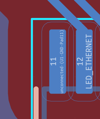
But, simple wires connected to 3.3V and GND did the trick, now I could see pins switch between high and low. 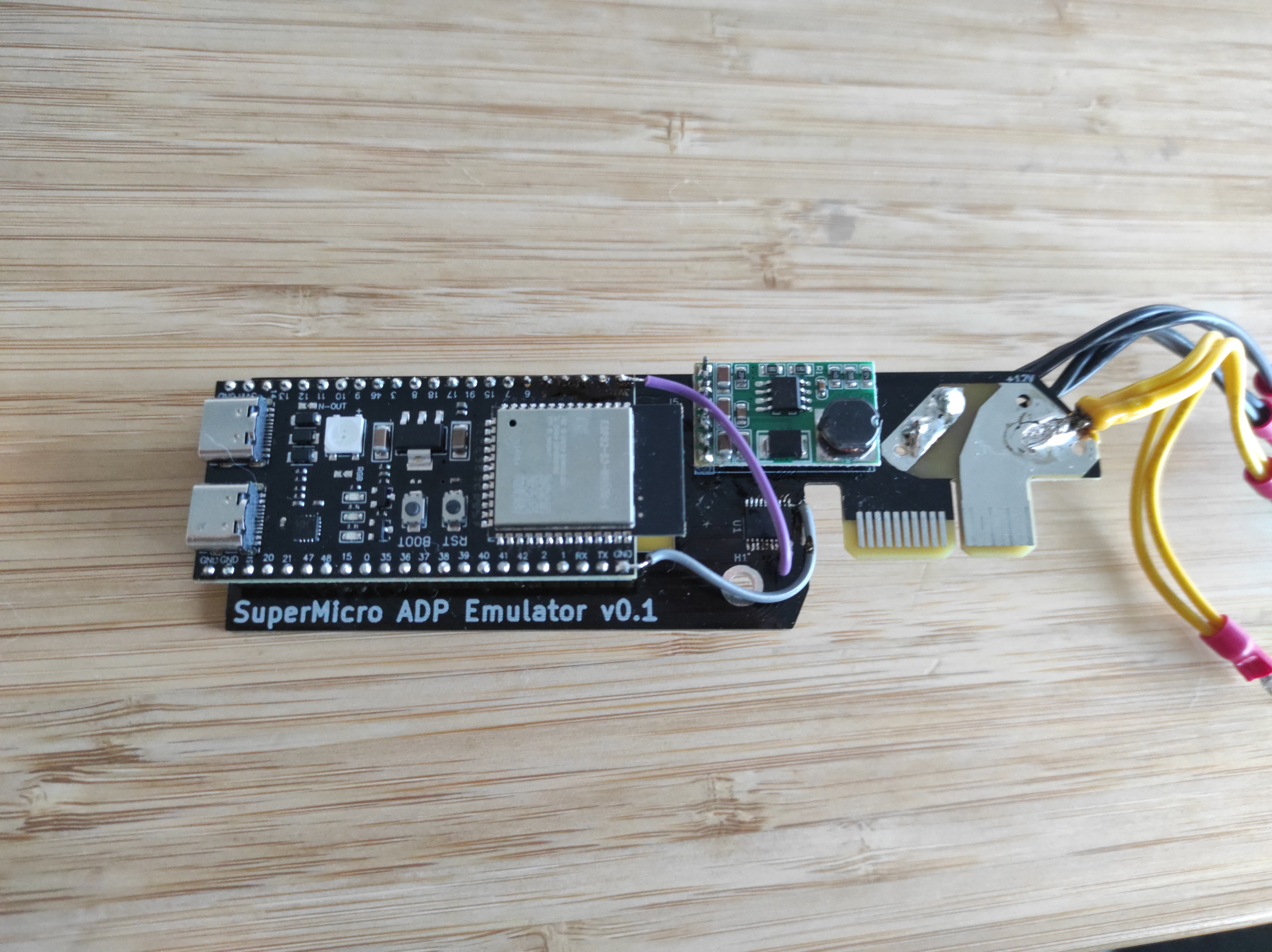
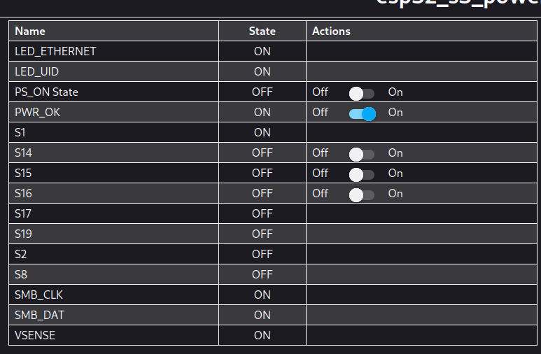 After a bit of tweaking:
- S1 pin is the actuall PS_ON pin.
- S17 pin was doing something strange continuously switching between high and low.
- S2 IS Buzzer
Anyway, with just pulling PWR_OK high it was able to boot, once again, nice. All 256Gb RAM is visible, power consumption of booted system is around 50W (5-10W power supply, 2W for esp32, 5W for IPMI, so actual usage by CPU and RAM is around 40W) and temps are around 55C idle (without any cooling). 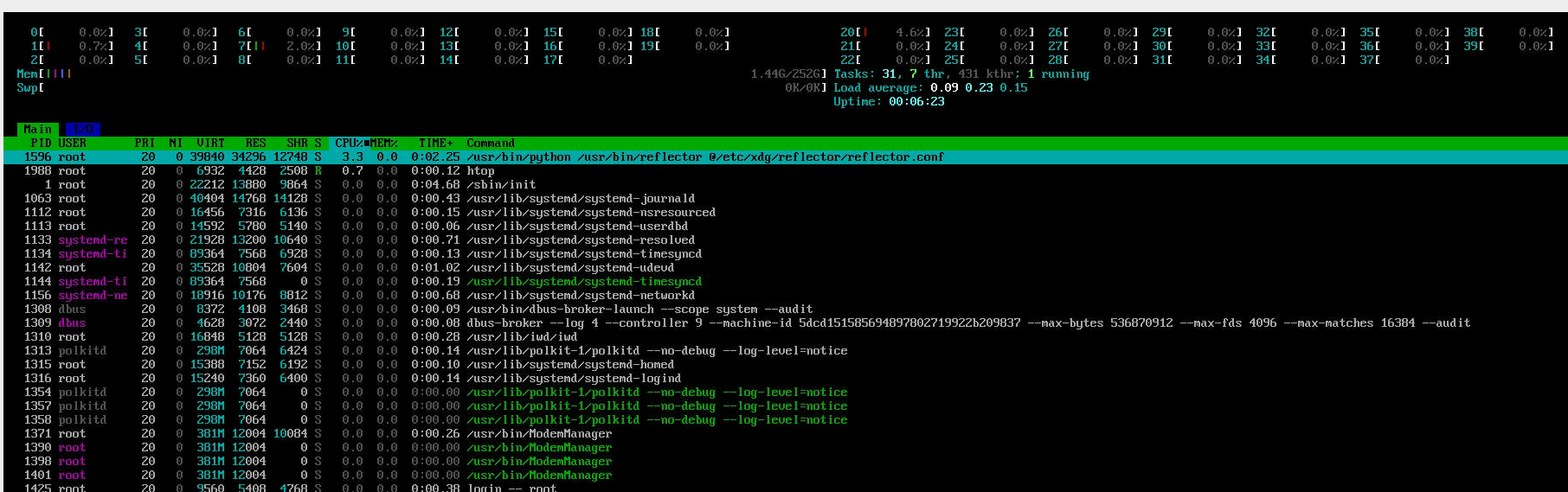
I next part, I will probably cover:
- update PCB
- figuring out cooling
- RAM upgrade
- (maybe) update CPU from Haswell to Broadwell
Thanks for reading, and until next time.
Next part: Running DeepSeek-R1 on refubrished blade server: 04 Cooling + Upgrades.
